4 regulator contact protection.
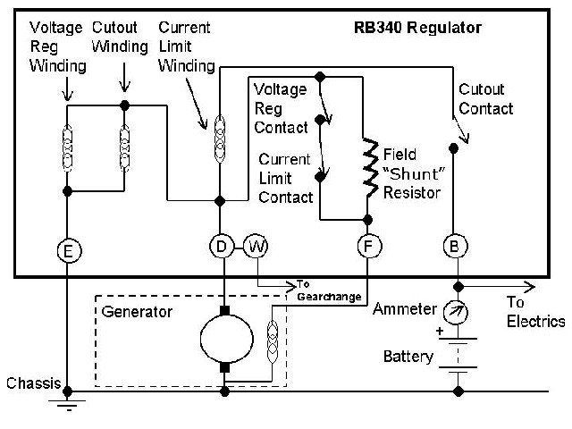
Lucas rb340 voltage regulator wiring diagram.
Proceed to test 6.
Connect one lead of voltmeter to ter b.
Hi all i got my lucas dynamo working a few days ago and was asked by makedoandmend1 if i could show how i wired it up.
Lucas fault diagnosis service manual fault diagnosis service manual lucas service manual created date.
The rb 3l0 and 6gc current voltage regulator build up of the unit.
Box terminals d and f.
Starter solenoid the definitive guide to solve all the.
The main point of this article is to provide a simple and easy to follow wiring diagram should you need to repair or rewire your classic motorbike.
5 a and a1 terminal reversal.
Lucas dr3a two speed wiper motors thorden.
Part 4 regulator tests.
Fuse panel diagram 73 87chevytrucks.
Less than battery voltage or zero re ctify bad ground or broken ground minal a.
Rb310 3 bobbin type with screw type electrical adjustment pages 10 16 oprinted in england no part of this book may be reproduced without permission.
3 typical car starting system diagram t amp x.
Circuits of the lucas current voltage regulator.
The device takes the form of a bi metallic spring that is located behind the tensioning spring of the regulator contact armature.
Any rb106 unit that has been used or has been kept in storage will have oxidation on its voltage regulator contacts and to a lesser extent on the cut out contacts.
Lucas rb340 voltage regulator solenoid ballast.
The other to terminal e on reading.
Let me know if.
I am basing this article on the lucas e3nl dynamo and mcr2 voltage regulator units fitted to my 1951 matchless g3ls but the same holds true for the majority of makes and models from the same era.
Printed in england.
1 finishing the contacts.
Mercedes cars parts and spares for old mercedeses.
Regulator ground connection in good reconnect generator leads to control order.
7 additional technical information rb106.
The lucas regulator units overcome this problem by using a temperature compensation device which makes its output conform more closely to the voltage characteristics of the battery.
Construction details of the rb 310 6gc and rb 340 control boxes.
Wire between terminal e and chassis.

